Hi.
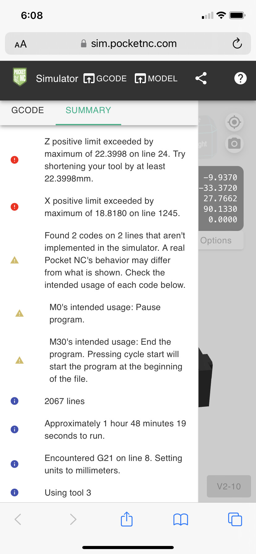
I have a question about my Gcode. Im trying to cut a part out of aluminium but i keep “exeeding” the axis limits. But infact i know i am not, the part should fit easy but still im getting “Linear move on line 24 would exceed joint 2’s positive limit
invalid params in linear command” error messeage. I have run the Gcode trough online simulator without no problem. Can someone please help me? Thank you.
Is your part programmed around the machine’s center of rotation? Or are you setting work offsets? If you are setting work offsets, we will need to know those values in order to simulate the program accurately.
In the case that you are programming around the center of rotation, or you know your work offsets are set correctly, the next thing to double check is your TLO (tool measurement). It is important that you have measured the tool number that the program is expecting. Once you have done this, please provide us with that value as well since it is also necessary for an accurate simulation.
My part is programmed around WCS.
I have done TLO on the tool. I have the extended spindle with a 30mm long tool on it. If i try to enter the gcode manualy step by stepp there is no problem. Also when i just move the machine manualy using keyboard comands no problem there either, it can reach wherever it needs.
It seems like the machine wants to back away from the part for some reason but it cant because its on the end of the rail. Its realy strange.
On the 24th line in the Gcode it is supossed to move toward the part and that is where it aparently fails.
line 24 of the Gcode"N85 Z39.471" so it means move to the position of 39.471mm and the Z axis is at 69.337mm so it should move toward the part not away.
The problem is your G54 offsets. The shift in Y is causing a shift in Z when A is at 90 degrees. The shift in X also causes your toolpaths to exceed the X travel limits further along. Make sure the G54 offsets represent the origin of your WCS setup when A is at 0.
Thank you for the responce. So if i understand correctly, G54 offset is set wrong because from the picture you sent me the machining is WAY off where it should be.
Correct, you can think of your G54 offset as the WCS Setup origin when A and B are at 0. You must input that value accurately for machining to be correct.
The G54 offset is your origin point. It should represent the WCS origin of your setup in Fusion 360. The way you mount your stock, though, may be different than how it is represented in Fusion, so you need to use the machine to know exactly where that point is. The link above demonstrates how to touch off the various faces, taking into account the radius of your tool, to appropriately set that point.
Ok so i set up the X and Y axis like the WCS biut still the same problem. I assume setting up Z axis is worthless since it has automatic tool measuring right?
X, Y and Z are necessary. Unlike in 3 axis machining, where the Z offset can be placed in your tool offset or your G54 offset, in 5 axis machining it’s important to represent the offsets in the appropriate place because transforms are applied when rotating the A and B axes. In this case, you are using Rotated Work Offsets (RWO) which takes the X, Y and Z coordinates of your G54 offset and rotates them by your A and B values (this is why your Y offset was affecting your Z travel initially). It does this so that the origin is in the right place after rotating.
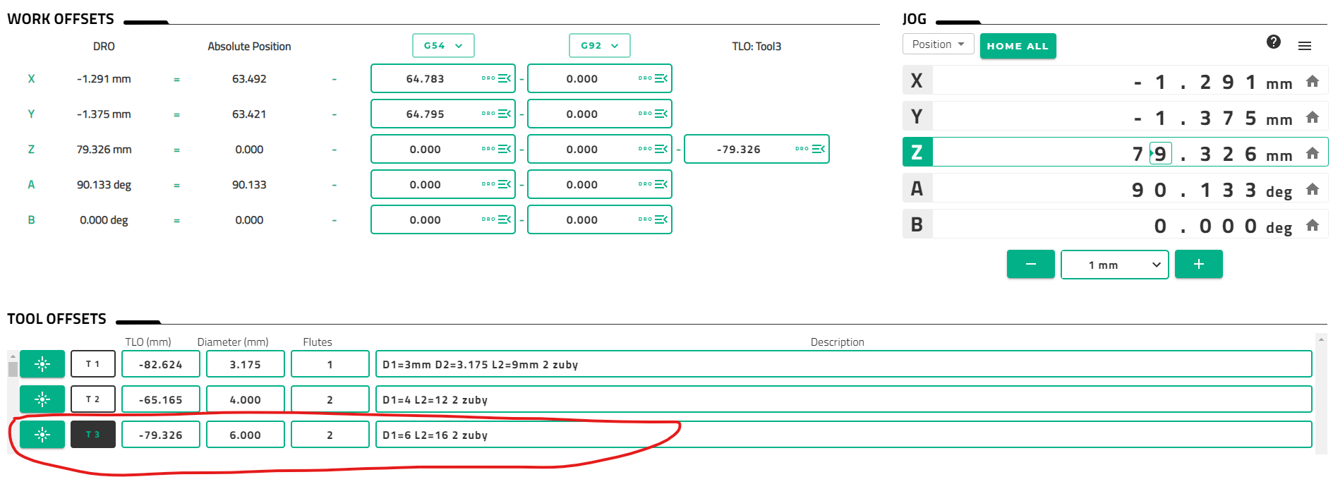
In the simulator, you can enter your G54 offsets by pressing the Stop button, then going to the Summary tab and scrolling down to the G54 offsets. Entering them there and then pressing Run Program will demonstrate how they affect your machine’s movements.